Gear Production
Issue link: http://gear.epubxp.com/i/262216
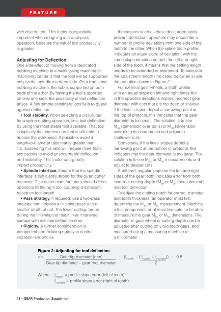
18—GEAR Production Supplement F E A T U R E with disc cutters. This factor is especially important when roughing is a dual-pass operation, because the risk of lost productivity is greater. Adjusting for Defection One side-effect of moving from a dedicated hobbing machine to a multitasking machine or machining center is that the tool will be supported only on the spindle interface side. On a traditional hobbing machine, the hob is supported on both ends of the arbor. By having the tool supported on only one side, the possibility of tool defection arises. A few simple considerations help to guard against defection: • Tool stability. When selecting a disc cutter for a spline-cutting operation, limit tool defection by using the most stable tool available. That tool is typically the shortest one that is still able to access the workpiece. If possible, avoid a length-to-diameter ratio that is greater than 1:5. Exceeding this ratio will require more than two passes to avoid unacceptable defection and instability. This factor can greatly impact productivity. • Spindle interface. Ensure that the spindle interface is suffciently strong for the given cutter diameter. Disc cutter manufacturers should direct operators to the right tool coupling dimensions based on tool length. • Pass strategy. If required, use a two-pass strategy that includes a fnishing pass with a smaller depth of cut. The lower cutting forces during the fnishing cut result in an improved surface with minimal defection error. • Rigidity. A further consideration is component and fxturing rigidity to control vibration tendencies. If measures such as these don't adequately prevent defection, operators may encounter a number of profle deviations from one side of the tooth to the other. When the spline tooth profle indicates an equal slope of deviation, with the same slope direction on both the left and right side of the tooth, it means that the setting length needs to be extended or shortened. To calculate the adjustment length (indicated below as x) use the equation shown in Figure 2. For external gear wheels, a tooth profle with an equal slope on left and right sides but in the opposite directions implies incorrect gear diameter with cuts that are too deep or shallow. If the lines' slopes depict a narrowing point at the top of protocol, this indicates that the gear diameter is too small. The solution is to see M dK (dimension over balls) or M dR (dimension over pins) measurements and adjust to shallower cuts. Conversely, if the lines' slopes depict a narrowing point at the bottom of protocol, this indicates that the gear diameter is too large. The solution is to see M dK or M dR measurements and adjust to deeper cuts. A different angular slope on the left and right sides of the gear tooth indicates error from both incorrect cutting depth (M dK or M dR measurement) and tool defection. To adjust the cutting depth for correct diameter and tooth thickness, an operator must frst determine the M dK or M dR measurement. Machine a test component, or at least two cuts, to be able to measure the gear M dK or M dR dimensions. The diameter of gear wheel or cutting depth can be adjusted after cutting only two tooth gaps, and measured using a measuring machine or a micrometer. Figure 2: Adjusting for tool defection x = Gear tip diameter (mm) ∙ (f Ha(left) - ( f Ha(left) + f Ha(right) )) ∙ 0.8 Gear tip diameter – gear root diameter 2 Where: f Ha(left) = profle slope error (left of tooth) f Ha(right) = profle slope error (right of tooth) 0314_MMS_Gear_MarkFeature.indd 18 2/13/2014 2:44:39 PM